Repel Nodes with a Linear Transform
I got this idea for what I’ll describe as a “net of nodes”. The nodes would be anchored to points, and when a mouse moves across them, the nodes attempt to repel the mouse while staying as anchored as possible to their point. The result acts as a much better explanation of what I wanted though:
I wanted each node’s position to be a function of the mouse’s position. This aspect lead to a lovely and simple design when all was said and done. To start writing this function, I first needed to define the system I was trying to create. I’ll explain how I did this by focusing on the behavior of a single node.
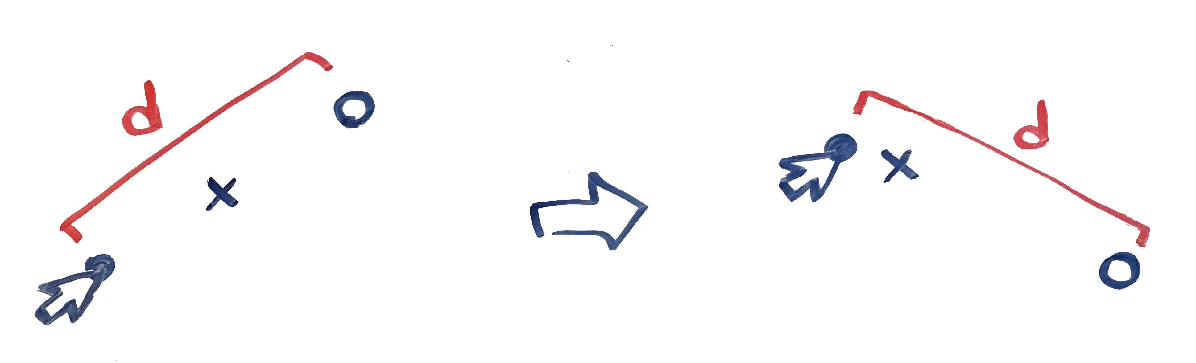
There are three points of interest for a node: the node’s anchor point (where the node rests when the mouse is far away), the node position, and the mouse position. Here’s how I’ll draw them:

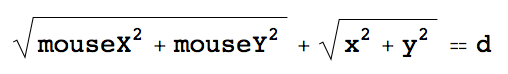
The first relationship to enforce between these points is that the distance between the mouse and the node’s actual position should be constant (we’ll actually revise this slightly in a bit, but for now, we’ll say it’s constant). Here’s a visual:
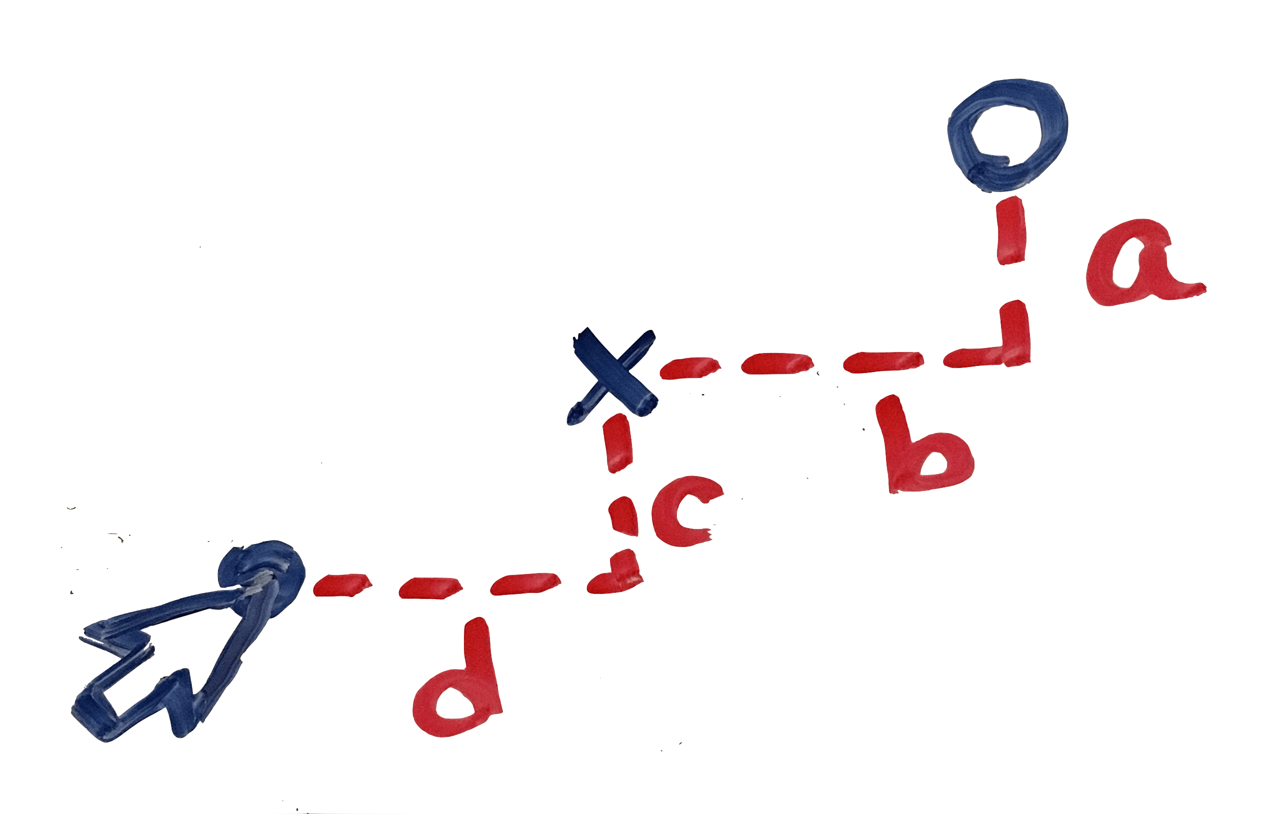
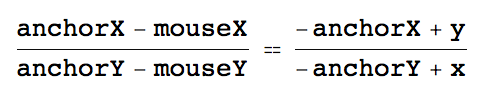
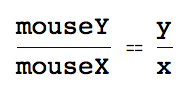
The second relationship to enforce is that the tangent of the angle between mouse and anchor should equal the tangent of the angle between anchor and node. This is more easily described as an equivalent ratio between the differences in heights and widths of the same pairs of points (a/b = c/d):
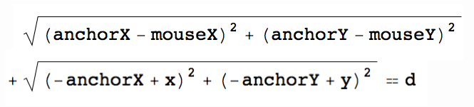
Together, we have the linear system of equations (x and y are nodeX and nodeY):
I gave these equations to Mathematica and told it to solve for {x, y}. Here’s a snippet of the result:

That’s looking fairly messy. There’s a simple observation we can make though, that will simplify this result greatly. Notice that if we assume that anchorX and anchorY are both 0, then the equations in our system become significantly less complex. As a result of this assumption, mouseX, mouseY, x, and y will have to be normalized accordingly. Here’s the revised equations with anchorX, anchorY = (0, 0):
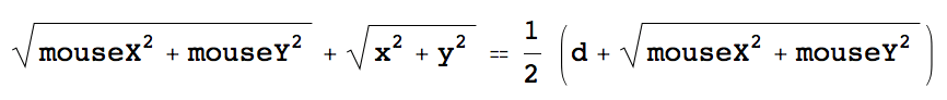
This is looking much better already. Solving for x and y in Mathematica yields a more manageable result as well. But before I show those Mathematica results, I’ll make one more alteration to the system of equations. Earlier, I mentioned that we’ll revisit this distance d. Now, I’d like to revise it so that the distance d reduces as the mouse gets closer to the anchor. This way, there will be a more convincing illusion that the node is fighting between the attracting force of the anchor and the repelling force of the mouse.
If we assert that (1) when the distance between the mouse and the anchor is d, then the distance between the mouse and the node should be d, and (2) when the distance between the mouse and the anchor is 0, then the distance between the mouse and the node should be d/2, then we end up with this revised equation 1:
Plugging for the last time into Mathematica and solving for x and y, we get this output (I’ve highlighted the parts that will be important to us):
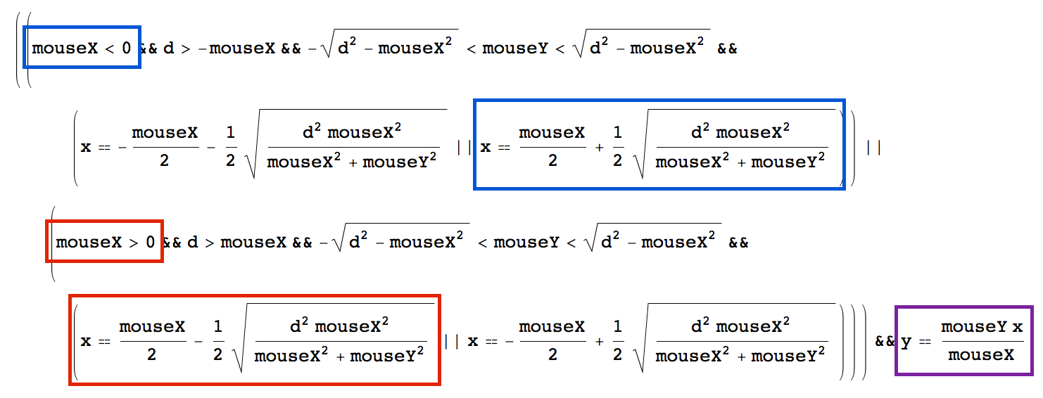
Now we’re ready for some JavaScript!
Here’s a function called oppose, which takes the values of mouseX, mouseY, anchorX, and anchorY, and returns the node’s position as x and y. We can take care of the normalization in this function for now, but it may become apparent later that we should do that elsewhere to save computation. But for now:
function oppose(anchorX, anchorY, mouseX, mouseY) {
    var mXN = mouseX - anchorX;
    var mYN = mouseY - anchorY;
    if (mXN < 0) {
      var offsetX = mXN/2 + s*Math.sqrt((mXN*mXN)/(mYN*mYN+mXN*mXN))/2;
    } else {
      var offsetX = mXN/2 - s*Math.sqrt((mXN*mXN)/(mYN*mYN+mXN*mXN))/2;
    }
    var offsetY = mYN*offsetX/mXN;
    return { left: offsetX + anchorX, top: offsetY + anchorY };
}
From this point, there’s freedom to create and maintain the nodes however you’d like. In my implementation, each node is a small, circular div. When a node is created, I store its anchorX and anchorY in its data attributes as x an y. This makes it easy to get those values back later, when I have to get each node anyway to adjust its position. I adjust the position of a node whenever the mouse moves, like so
$(".node").each(function() {
    var dist = distance(mouseX, mouseY, this.dataset.x, this.dataset.y);
    if (dist < d) {
        var newPoint = oppose(this.dataset.x, this.dataset.y, mouseX, mouseY);
        $(this).css(newPoint);
        ...
    }
)}
, where d is the same d from our mathematica equations.
The net is complete as far as the nodes are concerned. However, the edges are what complete the feel of the net.
To build the edges, I chose to draw SVG lines, using the anchor points of the nodes as the start and end points for the lines. I constructed them by iterating over each pair of nodes, drawing a line between them if the distance between them was less than d. Unfortunately, this runs in terrible O(n^2) time. Luckily, I won’t be drawing any nets big enough to notice. However, one could imagine an algorithm in O(nlog(n) + n) time, in which the nodes are sorted by x position, and then a pass of width 2d is made from left to right, connecting all nodes contained in the pass.
When building the edges in my implementation, I stored the id’s of the svg elements in arrays, indexed by node connections. I kept two arrays: edgesTo, and edgesFrom. To illustrate what I mean, here’s how I would obtain a list of the id’s of all edges connected to node 3: edgesTo[3].concat(edgesFrom[3]).
With this representation, we can complete the net update pass by adding the following after the oppose logic from before:
...
var edgesFromNode = edgesFrom[$(this).id];
for (var i = 0; i < edgesFromNode.length; i++) {
    $("#svg" + edgesFromNode[i]).attr({"x2": newPoint.left + Node.radius,
                                        "y2": newPoint.top + Node.radius});
}
var edgesToNode = Net.nodes[Net.nodeId($(this))].edgesTo;
for (var i = 0; i < edgesToNode.length; i++) {
  $("#svg" + edgesToNode[i]).attr({"x1": newPoint.left + Node.radius,
                                    "y1": newPoint.top + Node.radius});
}
Assuming the classes, nodes, and edges have been set up correctly, this update function works properly. On Chrome 50, a net of 200 nodes loads in ~820 milliseconds. The update function runs, on average, in 8ms (125 frames per second). Fine for our purposes! ◼